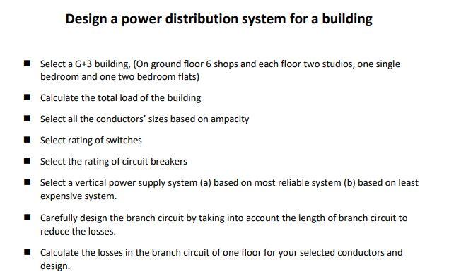
DIAGRAM Simple Electric Power Distribution Diagram Circuit Diagram
DIAGRAM Simple Electric Power Distribution Diagram Circuit Diagram Designing an electrical power distribution system requires a structured approach to ensure efficiency and safety. Start by defining load requirements and selecting appropriate voltage levels. Next, design the distribution layout and choose reliable equipment. Perform calculations and document the system thoroughly. A one-line diagram for an electric power distribution system is an electrical drawing that uses single lines and graphic symbols to illustrate the current path, voltage values, circuit disconnects, fuses, circuit breakers, transformers, and panelboards.. One-line diagrams use the most basic symbols because the intent of the drawing is to illustrate as clearly as possible the flow of current

Distribution transformer: A distribution transformer, also called as service transformer, provides final transformation in the electric power distribution system.It is basically a step-down 3-phase transformer.Distribution transformer steps down the voltage to 400Y/230 volts. Here it means, voltage between any one phase and the neutral is 230 volts and phase to phase voltage is 400 volts. power distribution 4 • At a distribution substation, a substation transformer takes the incoming transmission-level voltage (35 to 230 kV) and steps it down to several distribution primary circuits, which fan out from the substation. • Primary distribution lines are "medium-voltage" circuits, normally thought of Using software like AutoCAD, distribution design engineers draft power systems to bring electricity from distribution substations to homes. Designers have to calculate electricity usage and needs, prepare sketches, prescribe necessary equipment, estimate costs, update infrastructure, and more to make sure that power reaches customers and communities without jeopardizing the grid.
Electrical Distribution Design: The Basics Circuit Diagram
There are several configurations of distribution systems. Most distribution circuits are radial (both primary and secondary). Radial circuits have many advantages over networked circuits including: Easier fault current protection; Lower fault currents over most of the circuit; Easier voltage control; Easier prediction and control of power flows Electrical distribution system. An electrical electrical distribution system is a series of electrical circuits that delivers power in the proper proportion to homes, commercial businesses and industrial facilities. Regardless of the size and applications, the ultimate goal remains universal: the economic and safe delivery of adequate electric power to electrical equipment.

many specific design challenges, but certain basic principles are common to all. Such principles, if followed, will provide a soundly executed design. The basic principles or factors requiring consideration during design of the power distribution system include: Functions of structure, present and future Life and flexibility of structure
![[DIAGRAM] Simple Electric Power Distribution Diagram Circuit Diagram](https://www.researchgate.net/profile/Sen_Guo/publication/317207699/figure/fig1/AS:499379238445056@1496072696881/Schematic-diagram-of-a-generic-portion-of-Chinas-electric-power-system.png)