Infrared Transmitter 4 Steps Circuit Diagram
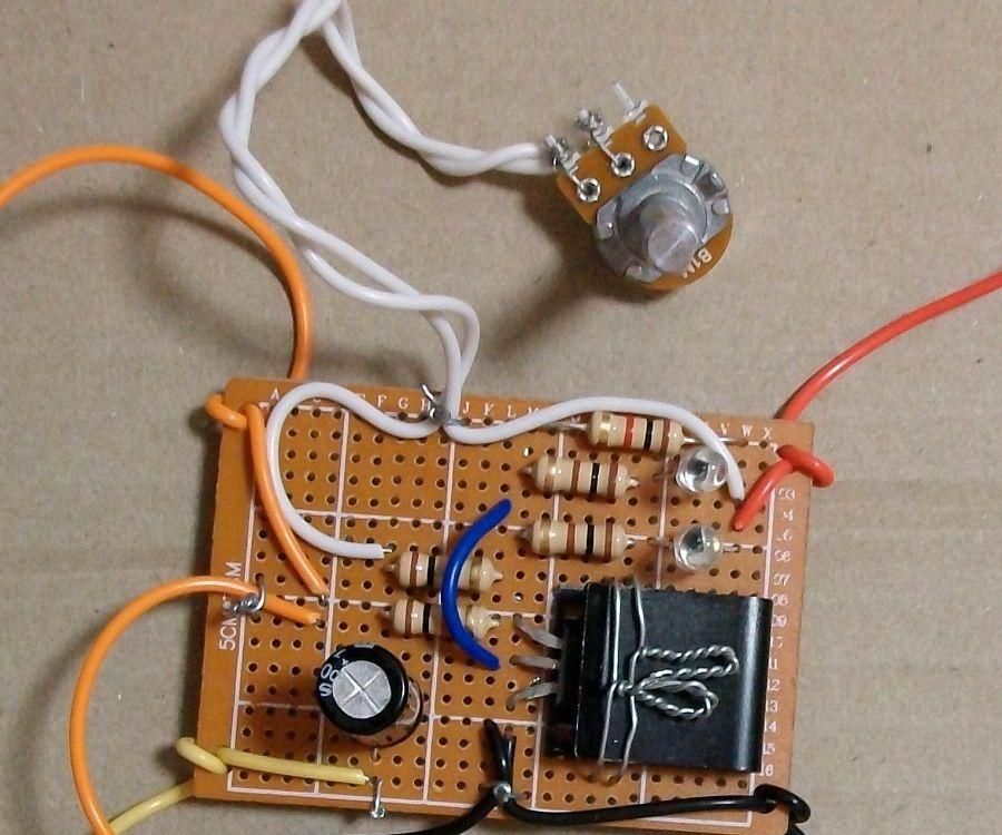
Infrared Transmitter 4 Steps Circuit Diagram Step-by-Step Guide to Building the Infrared Jammer Circuit. Assemble the Components: Place all components on a breadboard or solder them onto a perf board for a more permanent setup. Building an infrared jammer circuit is a great way to understand IR communication and how it can be disrupted. This simple yet effective project demonstrates
The Arduino UNO reads the state of three buttons. When a button is pressed, the Arduino uses the IRremote library to transmit a unique hexadecimal code encoded as an IR signal through the IR LED. Different codes can be assigned to each button press, allowing for communication of specific instructions to an IR receiver. Parts List. Arduino; IR
Infrared IR Transmitter and Receiver Circuit Circuit Diagram
IR LED's are commonly used in conjunction with the IR receiver to support a wireless communication between 2 or more devices. Step 3: 2. IR Receiver [PhotoDiode] Basically, an IR Module is a combination of a IR transmitter and receiver circuit. Infrared light emitted by the IR LED is detected by the Photodiode. LM358 Op-Amp IC is used

The optical transmitter circuit makes use of an LED to generate an AF controlled, infrared or visible stream of light which can be recognized by the phototransistor inside the receiver circuit. This phototransistor needs to have a peak sensitivity at the LED's peak emission wavelength in case the best possible efficiency is required.

Intro to IR Circuits : 9 Steps (with Pictures) Circuit Diagram
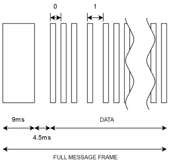
Tv ir remote uses InfraRed NEC Protocol for communication between infraRed remote and Tv itself. So I am going to make ir transmitter and Receiver using NEC Protocol that can be used for various purposes. Like controlling Appliances or Making IR Shark which would be a great Fun and easy to hack IR remotes.
![Visible Light Communication Circuit [using InfraRed] Circuit Diagram](https://www.homemade-circuits.com/wp-content/uploads/2021/04/demodulator-circuit-768x441.png)