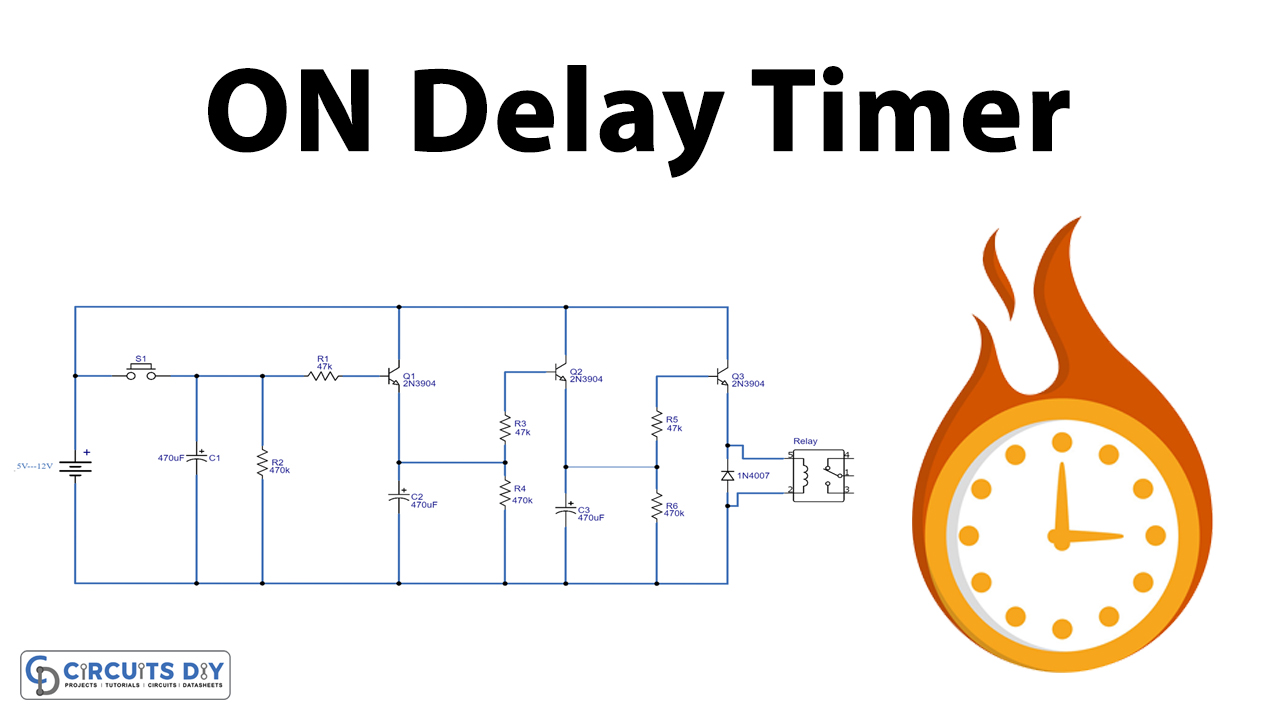
On Delay Timer Circuit using Three 2N3904 NPN Transistors Circuit Diagram
On Delay Timer Circuit using Three 2N3904 NPN Transistors Circuit Diagram The RC delay element is a way to create a time delay in your circuit by connecting a resistor and a capacitor. It's super simple. And very useful. The 'R' is a resistor, and the 'C' is a capacitor. That's where the 'RC' comes from. And here's how you connect the two: How does it work? A capacitor is kinda like a tiny little
In this video, I will explain the working of the transistor timer circuit, also known as delay timer or turn on circuit, which is an example of a hobby elect
Power-On Delay Timer Circuit Circuit Diagram
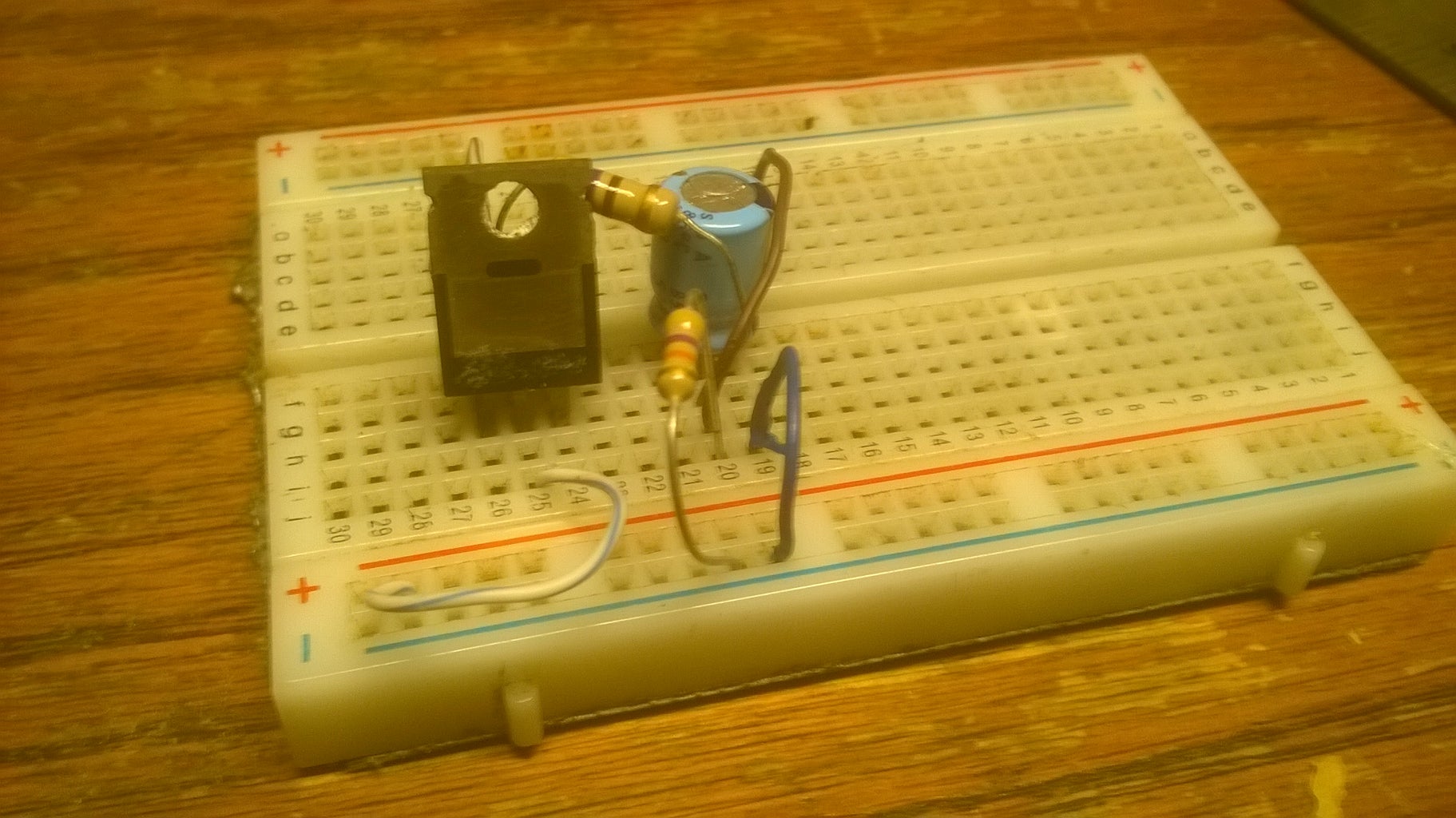
Its now time to test the circuit and add the extras. Add a button connecting the positive rail to the signal in line and connect an LED and a resistor to the signal out line. Apply power and push the button, if it lights up for a short time then fades out, the circuit is working properly and you can now add the relay if you do so choose. I want a delay circuit that does not need to be energized by a switch, I want the delay to start automatically when the mains power comes back. I only need the delay circuit, the mains switching part is taken care of already. I would appreciate you kind assistance, my efforts so far with 555 timers has not worked reliably. Andre Jordaan

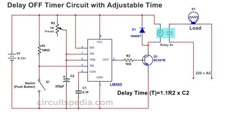
Using a Start Push-Button. The above design could be upgraded with a push-button to facilitate a push button start. This further ensures that the timer shuts off completely in case a power failure occurs while the circuit is operational, which in turn ensures that crucial loads like heater, or geyser are completely turned OFF during such situations. A simple power on delay circuit using IC 555 establishes a delay between power supply and circuit activation. When a trigger is received, the IC 555 runs in monostable mode, which causes it to produce a single output pulse for a predetermined amount of time. The timing network that establishes the delay time is made up of the resistor R1 and
How to Build a Delay Before Turn On Circuit with a 555 Timer Circuit Diagram
TIME DELAY SWITCH CIRCUIT: Have you ever wanted to delay the time ,of which an electric gadget at home,office and industry performs its function.This simple circuit,provides a solution. POWER SUPPLY CIRCUIT: The power supply circuit, consist of the 9v source from the battery, the 220uf electrolytic capacitor and the light indicator in In this circuit, we will show how to build a delay before turn on circuit with a 555 timer chip. A delay before turn on circuit is a circuit that once you apply power to it doesn't turn on the output right away. There is a delay before the output turns on. For this circuit, it's a few seconds delay. Once these few seconds pass, then the output
