precision Current Detection Circuit for Battery Circuit Diagram
precision Current Detection Circuit for Battery Circuit Diagram The DRV425 is an integrated magnetic fluxgate sensor integrated circuit that when implemented as a pair can be used for high-precision bus-bar measurement. 2 Current Sensing in Battery Management Systems SSZT475 - MAY 2019 (INCLUDING DATA SHEETS), DESIGN RESOURCES (INCLUDING REFERENCE DESIGNS), APPLICATION OR OTHER DESIGN ADVICE, WEB

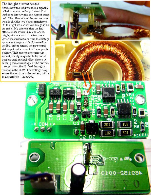
In summary, both resistive shunt and hall effect sensor circuits are used in battery management systems to sense circuit to monitor current and log abuse conditions. Resistive shunt circuits are desirable due to the zero current offset . Hall effect sensor circuits are desirable due to the electrical isolation that they provide. A current sensor circuit is a circuit that can measure the current flowing through it. Current sensor circuits are used extensively in systems such as battery management systems in order to detect the current to monitor for overcurrent, a short circuit, and the state of charge of the battery system.
Current sensing in battery management systems Circuit Diagram
A battery-management system's ability to accurately measure parameters such as pack Battery current sensors can be realized in two ways - shunt and magnetic - as shown in Figure 2 . The Automotive Shunt-Based ±500A Precision Current Sensing Reference Design offers battery current sensor solutions, providing excellent accuracy and

Current sensing circuit: This circuit measures the current flowing into or out of the battery pack. It helps in monitoring the charge and discharge rates and ensures the battery pack operates within safe limits. In conclusion, the future of battery management system circuit design is focused on increased integration, advanced monitoring and
Understanding current sensing in HEV/EV batteries Circuit Diagram
Measuring the voltage drop across a low-side current-shunt resistor is often the simplest method to determine battery/load current. Figure 2 shows an example low-side current-sensing circuit using the TLV379. The circuit in Figure 2 was designed to create a 0V-1.2V output voltage for a 0A-1A load current, i LOAD.