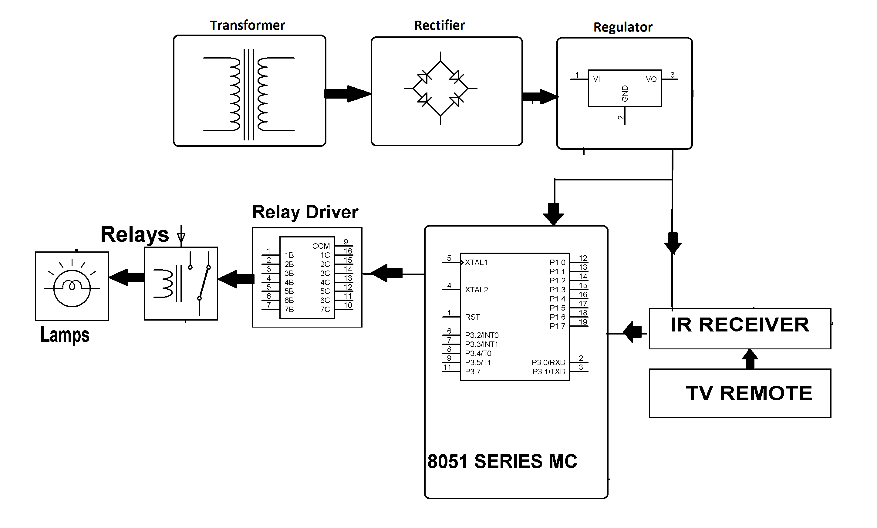
TV Remote Controlled Home Appliances Project Circuit Diagram
TV Remote Controlled Home Appliances Project Circuit Diagram The need for a remote control alert system that can control domestic appliances and various lighting points and sockets has often been a concern for users. At times users find it inconvenient and time consuming to go around turning their appliances on or off each time there is power outage or each time they are leaving the house for work.
The system uses an Arduino board to control home appliances and monitor sensors via Bluetooth from an Android app. Key features of the system include controlling lights, fans, TVs, AC units and more from the app, as well as smart door locking, garage door control, fire alarms, motion detection, and remote temperature monitoring. DCPs and corresponding DCPs to the Universal remote Control of the remote controller. Linux platform is applied as the operating platform of the control Box. UPnP Device executes the received UPnP Control commands. 3.2 Device Control Profile A remote controller controls the appliances by the transmission of messages.
RF Based Home Appliances Control System using Arduino Circuit Diagram
ability to remotely or automatically control things around the home without moving from place to place gives by RF remote control wall socket. A home appliances is a device or instrument design to perform a specific function. This project was design to control electrical devices that were connected to an AC power supply through the RF remote One of the main advantages of RF based remote control is that it can operate the appliances without the requirement of line of sight within its specified range efficiently. Figure.1 shows the basic overall design system to control four independent home appliances like TV, music system, room light and fan through a remote with four switches.

Using this remote, we can control the appliances within the range of 100 meters. This project has two sections, one is transmitter section and the other is receiver section. At transmitter section, we use HT12E encoder and at receiver section, we use HT12D decoder.
Design And Contruction Of A Microcontroller Based Rf Remote Control For ... Circuit Diagram
This project involves a 4-channel RF remote home automation system that can be used by a family. You can use this system to control any of your home appliances. You can control things such as LED light bulbs, fans, cell phone chargers, your refrigerator, and more.
